Driving Light Wiring

Ford SportTrac Forum

Help Support Ford SportTrac Forum:

This site may earn a commission from merchant affiliate links, including eBay, Amazon, and others.

Dads Tractors

Active Member
Joined
Nov 10, 2015
Messages
118
Reaction score
1
Location
Lincoln, NE
Can anyone verify my wiring schematics? Hooking driving lights to an extra oem fog light switch to an existing fog switch. Have a KC relay with 30, 85, 86, 87x2 terminals. Terminal 30 to + battery, terminal 85 to + battery, 87's to + on lights, terminal 86 to plug 3 of secondary (extra oem switch), plugs 4 and 5 jumped to original oem fog switch, and plug 6 of extra oem switch to + KC light cable. Oh and the KC lights - ground to chasis.

 
No, but here's two more sources to compare. :grin:
 
Last edited by a moderator:
Terminal 30 to + battery, terminal 85 to + battery, ...


Two leads to the battery positive; no switch?


... , 87's to + on lights ...


There should be an 87 (normally open) and an 87a (normally closed). Connecting both to power will power the lights regardless of switch position.


Electrical is much less confusing when using an actual schematic.


Assuming the KC relay is configured the same as an OEM relay:


- terminal 30 (high current for lights) from battery positive with a fuse before the relay

- terminal 85 (low current for relay coil) from switch positive (3) with a fuse before the switch

- terminal 86 to existing ground (4)

- terminal 87 (high current for lights) to fog light positive

- terminal 87a (for normally closed setup, as with the OEM high beam isolation circuit) assuming this is not to be utilized


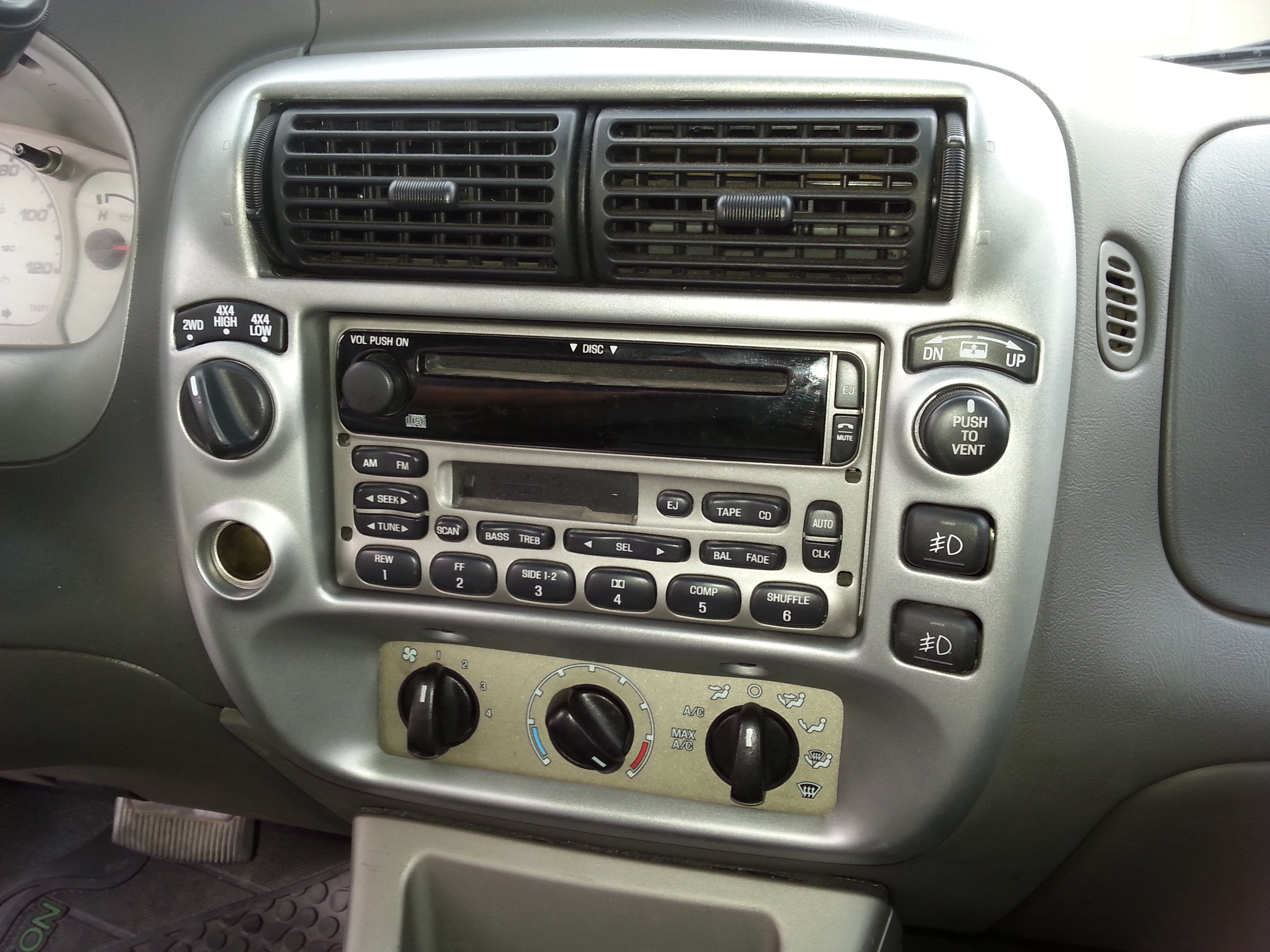
For an OEM switch, the wire on terminal 5 is for the switch background illumination (controlled by the dash lights dimmer). Also for an OEM switch, the wire on terminal 6 is for both the fog lights and the separate "On" indicator (internally wired).


And a line to ground for the lights.


Check the Fog Lights folder in my library for more schematics.
 
Last edited by a moderator:
My KC relay does not have a 87a but 2 87s that go to the lights + via a harness. I had been looking at the Secondary Switch Lighting Project and it looked that the battery + went to both the coil and contact side of tbe relay for an "available anytime" setup. Still a bit uncertain.
 
... and it looked that the battery + went to both the coil and contact side of tbe relay for an "available anytime" setup.


I used "fog lights", but this is related to driving lights, so ...


That project showed two ways to provide power to the relay coil - one from another switched source (i.e., parking lamps (OEM style) or some other utility), so that the other switched source must be on to provide power to the driving light relay coil and thereby turn on the driving lights when switched on, the other way is to jump the positive from the battery to the relay coil, so that the driving lights can be switched on at any time. (Note that wiring this way, the driving lights will remain on with the key removed and there will be no light-on reminder.)


As for the KC relay having two 87 terminals, and no differentiation between normally open and normally closed, without a picture or schematic, any input would be speculation.
 
Last edited by a moderator:
If your relay is a KC3300, then there is no normally closed state and, therefore, no 87a terminal, but two 87 terminals. Each of the 87 terminals connect to one light, but they do not both connect to both lights.
 
Last edited by a moderator:
When jumping the additional oem fog switch to the existing one to run driving lights would I need to add another fuse besides the one tied directly to the battery? Just wondering if the switches will be able to handle the load/supply?
 
That OEM fog light circuit from the battery (that goes to terminal 6 of the connector), has a 15A fuse, so high current is expected. I suspect that the KC lights pull more current than the OEM fog lights. If both sets of lights are on, the current will be at least double what the fog lights pull, probably more, and that will affect the circuit from the battery to wherever that circuit splits (one lead going to the fog and the other going to the driving lights). In that there is no way to reduce the current flowing through that circuit, an additional fuse would not help - where would it be placed?


You'd have to check the amps pulled by each set of lights to confirm, but it is possible that the higher current (with both sets of lights on) would blow the OEM 15A fuse. You may want to verify that the OEM switch for the driving lights can handle the current.


If it were me, I'd run a separate wire and fuse from the battery to the driving light switch. The appropriate gauge wire and rated fuse were probably included in the KC kit; I'd use them.
 
Last edited by a moderator:
I think you got it ... buzZzz-crackle-pop.


Your diagram implies that you intend to run a separate positive with fuse from the battery to relay terminal 30. This is a bit more work, I think it's worth the protection and peace of mind.
 
Thanks. Sorry about the length of this thread for what is probably an easy task for most. For me and wiring/circuitry no so much. I have everything done and wires run now just have to work on the bezel.
 
No apologies necessary.


I had to do some research, so I learned; you learned and that knowledge is now available to others. I think this is how it's supposed to work.
 
Well. Turned out good but got a little two toned action going on. Now going to paint my center console and let my radio and AC controls complement the instrument panel. Lights are all functional. Thanks all for the help.
d1f62ade6dcf7e36e29e1f1ac827b7f0.jpg
5188facf9a34ea2c177374d32e907a2f.jpg
 
You are welcome.


My OEM colors aren't much different than what you have - the color of my climate controls background has a slight gold tone that is nowhere else.


e7bd2248faf2d6a40f0a0a24ee7b30ea.jpg


Where did you find the Explorer Sport bezel?
 
Last edited by a moderator:

Latest posts

Top